


Grounding & Lightning Protection

Rayfield Communications employs years of real-world experience and a scientific, engineering process to design grounding systems that meet or exceed any site's grounding requirements. Our 4-Step Ground System Design Methodology is the process we use to achieve a predictable, controlled result. The purpose of the 4-Step Methodology is to provide a grounding system design with predictable performance. The result is that the grounding system performance will be known prior to installation. It eliminates the need for continued efforts and site visits. Each grounding system we design is made for the specific site where it will be installed and to meet or exceed our client's requirements.
Soil Resistivity Testing 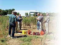
Soil resistivity data is the basis of any predictable grounding system design. It represents the resistance of the earth to the flow of electrical current. Soil resistivity is determined by the type of soil and its moisture and electrolyte content and temperature. Two methods are available to determine the resistivity at a particular location. The most common and accurate is the 4-Point Wenner method. The 4-Point method places 4 probes in the earth. A current flow is established through the outer probes and the resulting voltage drop is measured across the inner probes. Several locations should be tested. Remember that the data is being used to design the ground system and predict the performance after installation. The more data available, the more confidence you can have in the prediction. Soil samples can also be bench tested. The obvious limitation is that only a small amount of soil is tested. If several samples are collected from different depths and different locations at the site, an adequate design can be accomplished.
Site Audit Surveys 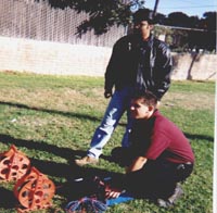
Rayfield Communications' personnel are available for complete site audits. Previous clients have included Sprint, Jasper County Emergency Services, Dade County Emergency Services, Ozark County Emergency Services, Barry County 911, Douglas County Office of Emergency Management, City of Ava, and Aurora Police and Fire. Some of the key areas reviewed at a Site Audit/Survey are:
A full written report with observations, recommendations, pictures and drawings of the grounding design recommendation is provided upon completion.
Installation Services 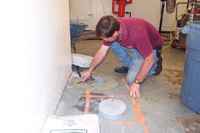
Rayfield Communications provides turnkey installation services for our customers. Our personnel will arrange the complete project from the coordination of sub-contractors, installation, connection to the electrical service and final compliance testing. Rayfield Communications can provide the complete turnkey project, or any part of it. We also offer project supervision - the customer arranges and coordinates the project and Rayfield Communications provides the supervision and final compliance testing to ensure the installation meets the performance specification. Some clients need only to have the final compliance testing performed by Rayfield Communications to ensure that the installation was done properly. A complete written report is provided with any of the above services.
Ground System Compliance Testing 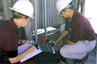
The ground system is critical for the protection, reliability, and performance of sensitive equipment. Verifying that a newly installed grounding system, or your "old" one meets the specification is very important for many reasons.
Two methods are commonly utilized for compliance testing. The first is the 3-Point Fall of Potential test. This IEEE standard is the most recognized. The vast majority of these tests are invalid. There are two primary reasons. One, the ground system must be electrically isolated, which is often impossible to do. If not isolated, the test result will always be extremely low, even if the system has several hundred ohms of resistance. Two, the test may require a probe to be installed several hundred feet from the system under test. This is often impractical, but if not done, the test will be invalid. The second method of test is using the AEMC 3711 Clamp-On meter. The meter is extremely convenient when properly used. It must be installed such that all the current it induces flows through the ground system and returns via the utility neutral. |